某企业网络及服务器规划与设计(小学期作业)
iksjls 2024-07-15 14:37:02 阅读 94
目录
一、项目需求与设计
1.1项目需求
1.1 网络拓扑
1.2 设备地址和技术规划
二、项目所需环境
2.1 硬件环境
2.2 软件环境
三、项目实现过程
3.1网络配置
3.1.1 MSTP
3.1.2 VRRP
3.1.3 OSPF
3.1.4 ACL
3.1.5 LACP
3.1.6 Telnet
3.2 服务器配置
3.2.1 WEB
3.2.2 DNS
3.2.3 FTP
3.2.4 DHCP
四、项目测试结果
4.1 服务器测试
4.1.1 DNS
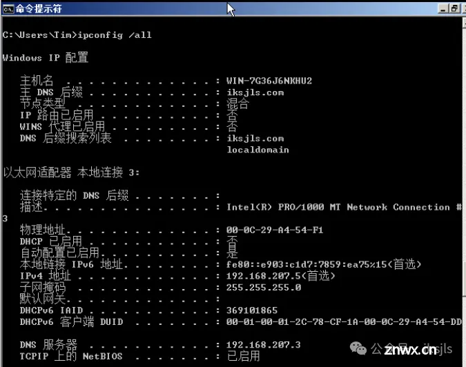
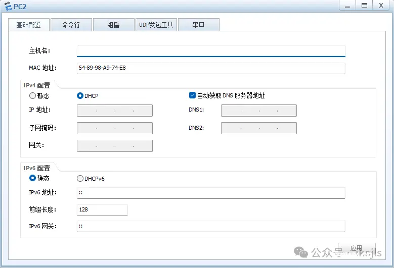
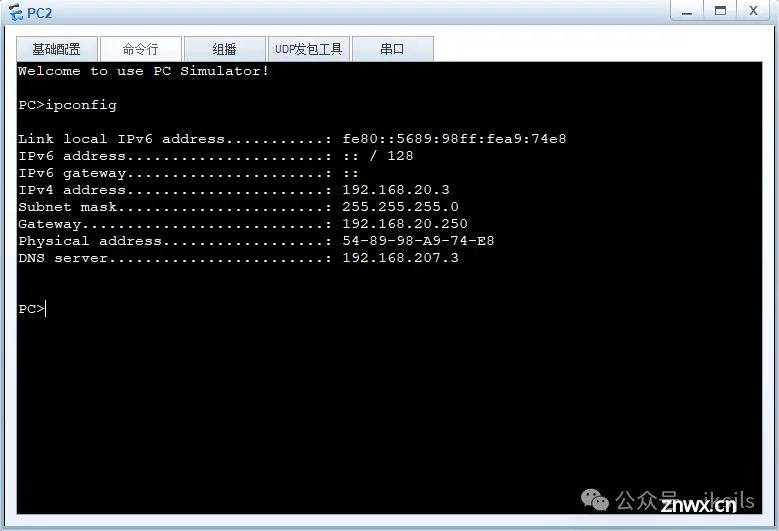
4.1.2 DHCP
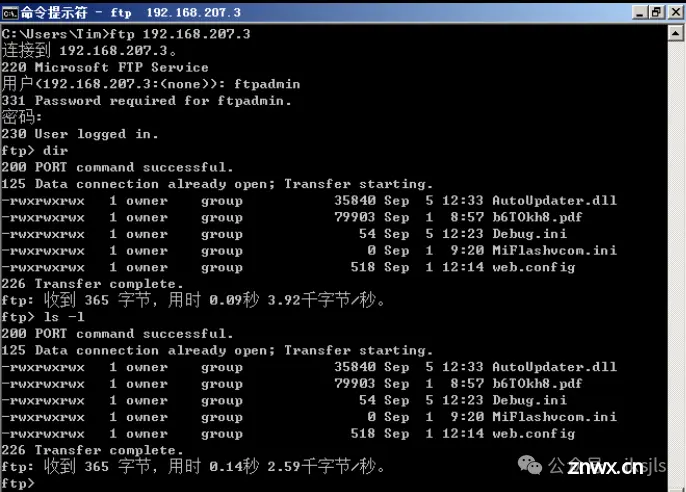
4.1.3 FTP
4.1.4 WEB
4.2 网络测试
4.2.1 链路聚合
4.2.2 主备备份
4.2.3 远程登录
五、项目总结和体会
一、项目需求与设计
1.1项目需求
1.规划企业网络及服务器配置方案,相同部门可以相互访问不同部门之间不能相互访问,楼内有各种必要的办公系统和服务器等。
2.该企业需要建立局域网,采用双出口的网络接入模式,一条链路接入Internet1,一条链路接入Internet2,使用三层交换机接入互联网络。
3.该企业采用基于三层交换机的双核心网络,分别用OSPF、MSTP、VRRP、主备备份、LACP 链路聚合和负载均衡,VTP、VLAN等技术实现。
4.该企业安全方面有访问控制列表ACL。
5.该企业规划了服务器区域,包括基于WIN 2008 Server操作系统的WEB、DNS服务器,还有FTP和DHCP服务器。
6.目前该企业有四个主要的部门,人资部(V10)、营销部(V20)、财务部(V30)、物流部(V40)。
1.1 网络拓扑
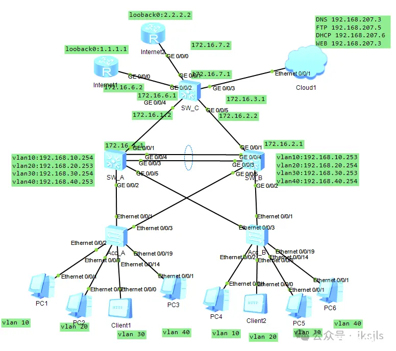
1.2 设备地址和技术规划
| 所属部门
| 所属VLAN
| 地址空间
| 网关
|
| 人力资源部
| VLAN10
| 192.168.10.X/24
| 192.168.10.253/24
|
| 192.168.10.254/24
| |||
| 市场营销部
| VLAN20
| 192.168.20.X/24
| 192.168.20.253/24
|
| 192.168.20.254/24
| |||
| 财务部
| VLAN30
| 192.168.30.X/24
| 192.168.30.253/24
|
| 192.168.30.254/24
| |||
| 信息部
| VLAN40
| 192.168.40.X/24
| 192.168.40.253/24
|
| 192.168.40.254/24
|
| 设备名称
| 设备型号
| 接口
| IP地址
| 用途
|
| PCX
| PC
| E0/0/1
| 192.168.X.X/24
| 模拟计算机终端
|
| ClientX
| PC
| E0/0/0
| 192.168.X.X/24
| 验证web和ftp
|
| SW_A
| S5700-SW_A
| Vlanif10
| 192.168.10.254/24
| 模拟网关
|
| Vlanif20
| 192.168.20.253/24
| |||
| Vlanif30
| 192.168.30.254/24
| |||
| Vlanif40
| 192.168.40.253/24
| |||
| Vlanif300
| 172.16.1.1/24
| |||
| SW_B
| S5700-SW_B
| Vlanif10
| 192.168.10.253/24
| 模拟网关
|
| Vlanif20
| 192.168.20.254/24
| |||
| Vlanif30
| 192.168.30.253/24
| |||
| Vlanif40
| 192.168.40.254/24
| |||
| Vlanif400
| 172.16.2.1/24
| |||
| SW_C
| S5700-
SW_C
| Vlanif100
| 192.168.10.254/24
| 模拟网关
|
| Vlanif200
| 192.168.20.253/24
| |||
| Vlanif300
| 192.168.30.254/24
| |||
| Vlanif400
| 192.168.40.253/24
| |||
| Vlanif500
| 172.16.1.1/24
|
| 各设备中主要实现的功能和应用的相关技术
| |
| 接入设备名称
| 相应技术
|
| Acc_A
| 接口或vlan地址/vlan基本划分,ACL,console密码
|
| Acc_B
| 接口或vlan地址/vlan基本划分,ACL,console密码
|
| SW_A
| 接口或vlan地址/vlan的基本划分
OSPF,VRRP,MSTP负载均衡,LACP链路聚合,DHCP中继
|
| SW_B
| 接口或vlan地址/vlan的基本划分OSPF,
VRRP,MSTP负载均衡,LACP链路聚合,DHCP中继
|
| SW_C
| 接口或vlan地址/vlan的基本划分OSPF,静态路由,路由引入
|
| Internet1
| 静态路由,默认路由
|
| Internet2
| 静态路由,默认路由
|
| Cloud1
| 模拟内网的DNS、FTP、DHCP、WEB服务器
|
二、项目所需环境
2.1 硬件环境
| 硬件类型
| 型号
| 数量
|
| 路由器
| AR2220
| 2
|
| 三层交换机
| S5700
| 3
|
| 二层交换机
| S3700
| 3
|
| 服务器
| Cloud1
| 1
|
2.2 软件环境
Ensp模拟器、VMware-workstation、WindowsServer2008
三、项目实现过程
3.1网络配置
3.1.1 MSTP
SW_A
<code>[SW_A]stp mode mstp
[SW_A]stp region-config
[SW_A-mstp-region]region-name iksjls
[SW_A-mstp-region]revision-level 1
[SW_A-mstp-region]instance 1 vlan 10 30
[SW_A-mstp-region]instance 2 vlan 20 40
[SW_A-mstp-region]active region-config
[SW_A-mstp-region]
[SW_A-mstp-region]stp instance 1 root pri
[SW_A]stp instance 2 root sec
-------------------------------------------------------------------
SW_B
[Huawei]sys SW_B
[SW_B]stp mode mstp
[SW_B]stp region-config
[SW_B-mstp-region]region-name iksjls
[SW_B-mstp-region]revision-level 1
[SW_B-mstp-region]instance 1 vlan 10 30
[SW_B-mstp-region]instance 2 vlan 20 40
[SW_B-mstp-region]active region-config
[SW_B-mstp-region]
[SW_B-mstp-region]stp instance 2 root pri
[SW_B]stp instance 1 root sec
3.1.2 VRRP
SW_A
[SW_A-Vlanif10]vrrp vrid 10 vir 192.168.10.250
[SW_A-Vlanif10]vrrp vrid 10 pri 200
[SW_A-Vlanif10]int vlan20
[SW_A-Vlanif20]vrrp vrid 20 vir 192.168.20.250
[SW_A-Vlanif20]int vlan 30
[SW_A-Vlanif30]vrrp vrid 30 vir 192.168.30.250
[SW_A-Vlanif30]vrrp vrid 30 pri 200
[SW_A-Vlanif30]int vlan 40
[SW_A-Vlanif40]vrrp vrid 40 vir 192.168.40.250
-------------------------------------------------------------------
SW_B
[SW_B-Vlanif10]vrrp vrid 10 vir 192.168.10.250
[SW_B-Vlanif10]int vlan20
[SW_B-Vlanif20]vrrp vrid 20 vir 192.168.20.250
[SW_B-Vlanif20]vrrp vrid 20 pri 200
[SW_B-Vlanif20]int vlan 30
[SW_B-Vlanif30]vrrp vrid 30 vir 192.168.30.250
[SW_B-Vlanif30]int vlan 40
[SW_B-Vlanif40]vrrp vrid 40 vir 192.168.40.250
[SW_B-Vlanif40]vrrp vrid 40 pri 200
3.1.3 OSPF
SW_A
[SW_A]ospf 1 router-id 1.1.1.1
[SW_A-ospf-1]area 0.0.0.0
[SW_A-ospf-1-area-0.0.0.0]network 192.168.10.0 0.0.0.255
[SW_A-ospf-1-area-0.0.0.0]network 192.168.20.0 0.0.0.255
[SW_A-ospf-1-area-0.0.0.0]network 192.168.30.0 0.0.0.255
[SW_A-ospf-1-area-0.0.0.0] network 192.168.40.0 0.0.0.255
[SW_A-ospf-1-area-0.0.0.0] network 172.16.1.0 0.0.0.255
-------------------------------------------------------------------
SW_B
[SW_B] ospf 1 router-id 2.2.2.2
[SW_B-ospf-1] area 0.0.0.0
[SW_B-ospf-1-area-0.0.0.0]network 192.168.10.0 0.0.0.255
[SW_B-ospf-1-area-0.0.0.0]network 192.168.20.0 0.0.0.255
[SW_B-ospf-1-area-0.0.0.0]network 192.168.30.0 0.0.0.255
[SW_B-ospf-1-area-0.0.0.0]network 192.168.40.0 0.0.0.255
[SW_B-ospf-1-area-0.0.0.0]network 172.16.2.0 0.0.0.255
-------------------------------------------------------------------
SW_C
[SW_C]ospf 1 router-id 3.3.3.3
[SW_C-ospf-1] area 0.0.0.0
[SW_C-ospf-1-area-0.0.0.0] network 172.16.1.0 0.0.0.255
[SW_C-ospf-1-area-0.0.0.0] network 172.16.2.0 0.0.0.255
[SW_C-ospf-1-area-0.0.0.0] network 192.168.207.0 0.0.0.255
3.1.4 ACL
[Acc_A]
Acl 3001
Rule permit ip source 192.168.10.0 0.0.0.255 destination 192.168.10.0 0.0.0.255
Rule deny ip source any destination 192.168.20.0 0.0.0.255
Rule deny ip source any destination 192.168.30.0 0.0.0.255
Rule deny ip source any destination 192.168.40.00.0.0.255
Int e0/0/2
traffic-filter inbound acl 3001
acl 3002
rule permit ip source 192.168.20.0 0.0.0.255 destination 192.168.20.0 0.0.0.255
rule deny ip source any destination 192.168.10.00.0.0.255
rule deny ip source any destination 192.168.30.00.0.0.255
rule deny ip source any destination 192.168.40.00.0.0.255
inte0/0/8
traffic-filter inbound acl 3002
acl 3003
rule permit ip source 192.168.30.0 0.0.0.255 destination 192.168.30.0 0.0.0.255
rule deny ip source any destination 192.168.10.0 0.0.0.255
rule deny ip source any destination 192.168.20.0 0.0.0.255
rule deny ip source any destination 192.168.40.0 0.0.0.255
int e0/0/14
traffic-filter inbound acl 3003
acl 3004
rule permit ip source 192.168.40.0 0.0.0.255 destination 192.168.40.0 0.0.0.255
rule deny ip source any destination 192.168.10.0 0.0.0.255
rule deny ip source any destination 192.168.20.0 0.0.0.255
rule deny ip source any destination 192.168.30.0 0.0.0.255
int e0/0/19
traffic-filter inbound acl 3004
-------------------------------------------------------------------
Acc_B
acl 3001
rule permit ip source 192.168.10.0 0.0.0.255 destination 192.168.10.0 0.0.0.255
rule deny ip source any destination 192.168.20.0 0.0.0.255
rule deny ip source any destination 192.168.30.0 0.0.0.255
rule deny ip source any destination 192.168.40.0 0.0.0.255
int e0/0/2
traffic-filter inbound acl 3001
acl 3002
rule permit ip source 192.168.20.0 0.0.0.255 destination 192.168.20.0 0.0.0.255
rule deny ip source any destination 192.168.10.0 0.0.0.255
rule deny ip source any destination 192.168.30.0 0.0.0.255
rule deny ip source any destination 192.168.40.0 0.0.0.255
int e0/0/8
traffic-filter inbound acl 3002
acl 3003
rule permit ip source 192.168.30.0 0.0.0.255 destination 192.168.30.0 0.0.0.255
rule deny ip source any destination 192.168.10.0 0.0.0.255
rule deny ip source any destination 192.168.20.0 0.0.0.255
rule deny ip source any destination 192.168.40.0 0.0.0.255
int e0/0/14
traffic-filter inbound acl 3003
acl 3004
rule permit ip source 192.168.40.0 0.0.0.255 destination 192.168.40.0 0.0.0.255
rule deny ip source any destination 192.168.10.0 0.0.0.255
rule deny ip source any destination 192.168.20.0 0.0.0.255
rule deny ip source any destination 192.168.30.0 0.0.0.255
int e0/0/19
traffic-filter inbound acl 3004
3.1.5 LACP
SW_A
[SW_A]int eth-trunk 1
[SW_A-Eth-Trunk1]mode lacp
[SW_A-Eth-Trunk1]int g0/0/3
[SW_A-GigabitEthernet0/0/3]eth-trunk 1
[SW_A-GigabitEthernet0/0/3]int g0/0/4
[SW_A-GigabitEthernet0/0/4]eth-trunk 1
[SW_A-GigabitEthernet0/0/4]lacp priority 100
[SW_A-GigabitEthernet0/0/4]int eth-trunk 1
[SW_A-Eth-Trunk1]max active-linknumber 2
[SW_A-Eth-Trunk1]int g0/0/3
[SW_A-GigabitEthernet0/0/3]lacp priority 100
[SW_A-GigabitEthernet0/0/3]int g0/0/4
[SW_A-GigabitEthernet0/0/4]lacp priority 100
[SW_A-GigabitEthernet0/0/4]vlan batch 10 20 30 40 300 400
[SW_A]int eth-trunk 1
[SW_A-Eth-Trunk1]port link-type trunk
[SW_A-Eth-Trunk1]p t a v 10 20 30 40 300 400
SW_B
[SW_B]int eth-trunk 1
[SW_B-Eth-Trunk1]mode lacp
[SW_B-Eth-Trunk1]int g0/0/3
[SW_B-GigabitEthernet0/0/3]eth-trunk 1
[SW_B-GigabitEthernet0/0/3]int g0/0/4
[SW_B-GigabitEthernet0/0/4]eth-trunk 1
[SW_B-GigabitEthernet0/0/4]lacp priority 100
[SW_B-GigabitEthernet0/0/4]int eth-trunk 1
[SW_B-Eth-Trunk1]max active-linknumber 2
[SW_B-Eth-Trunk1]int g0/0/3
[SW_B-GigabitEthernet0/0/3]lacp priority 100
[SW_B-GigabitEthernet0/0/3]int g0/0/4
[SW_B-GigabitEthernet0/0/4]lacp priority 100
[SW_B-GigabitEthernet0/0/4]
[SW_B-GigabitEthernet0/0/4]
[SW_B-GigabitEthernet0/0/4]vlan batch 10 20 30 40 300 400
[SW_B]int eth-trunk 1
[SW_B-Eth-Trunk1]port link-type trunk
[SW_B-Eth-Trunk1]p t a v 10 20 30 40 300 400
3.1.6 Telnet
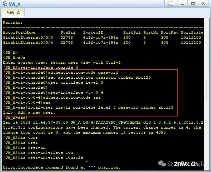
SW_A
user-interface vty 0 4
authentication-mode aaa
aaa
local-user iksjls privilege level 3 password cipher abc123
其余各设备的telnet配置都一致,这里便不在赘述
3.2 服务器配置
3.2.1 WEB
安装并打开IIS服务
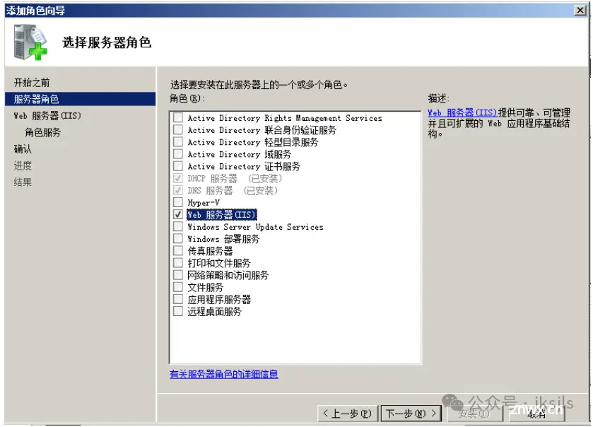
添加网站

添加网站绑定

2、配置主目录
步骤1:在C盘根目录下建立一个名为“site1”的文件夹;
步骤2:操作——编辑网站——基本配置

配置默认文档
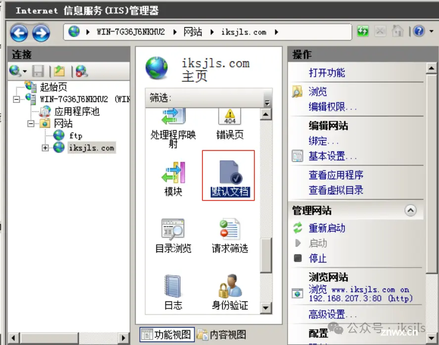
添加并编辑index.html文档
这里可以打开index.html,编辑成自己想要的样子
步骤1:进入C:/site1文件夹,步骤2:用记事本编辑index.html文件

3.2.2 DNS
安装DNS服务器
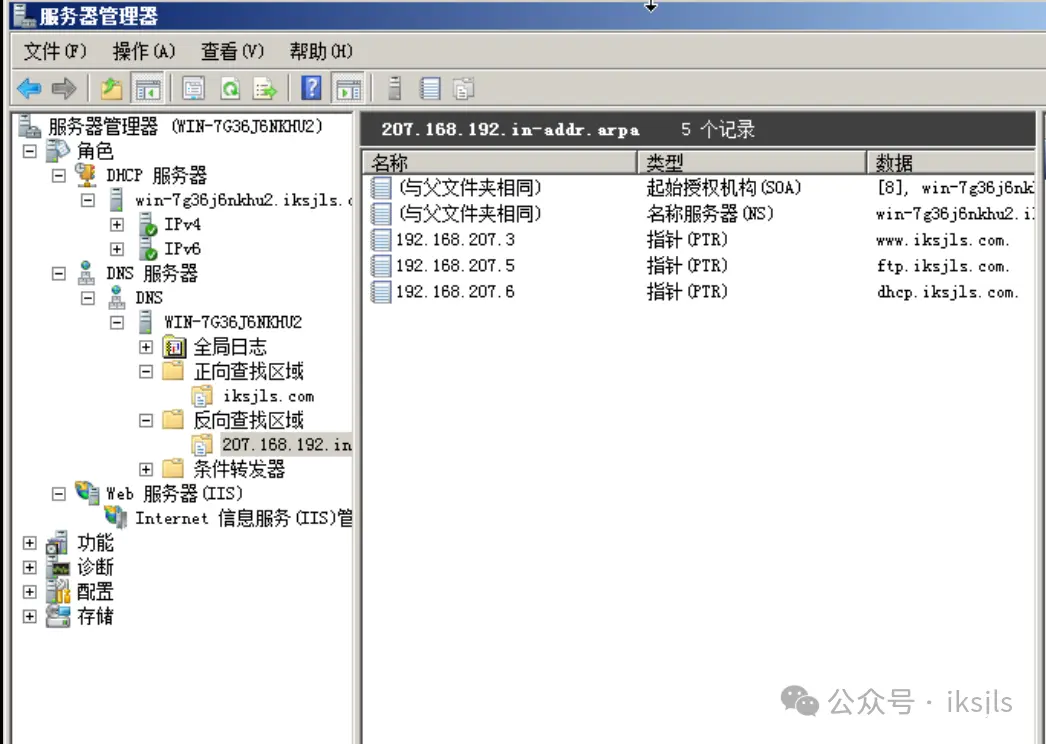
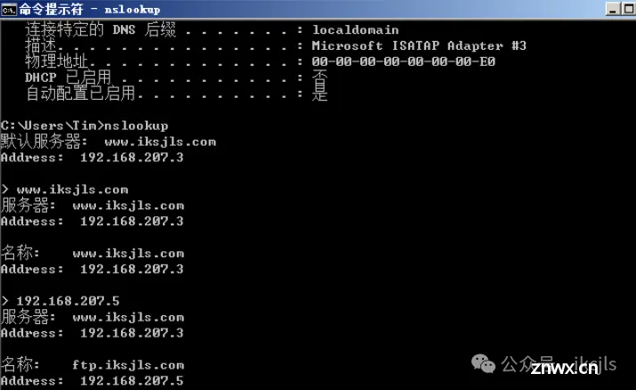
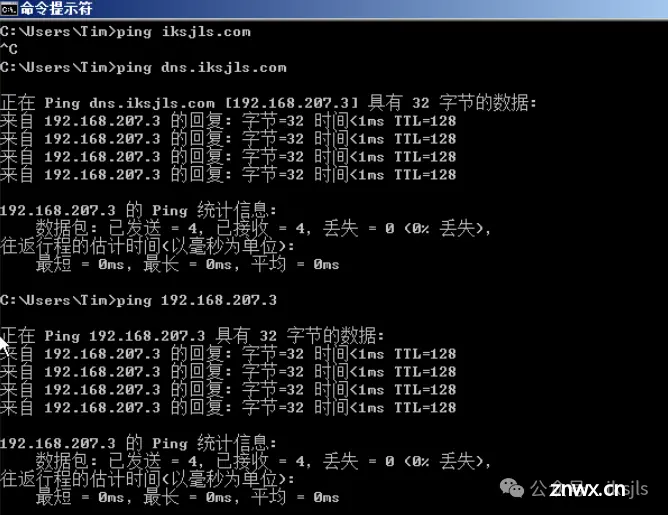
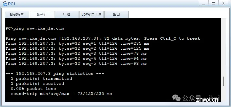
添加正向查找域“iksjls.com”,添加记录1“www.iksjls.com”对应192.168.207.3/24地址,添加记录2“dns.iksjls.com”对应192.168.207.3/24地址,添加记录3“ftp.iksjls.com”对应192.168.207.5/24地址,“dhcp.iksjls.com”对应192.168.207.6/24地址。
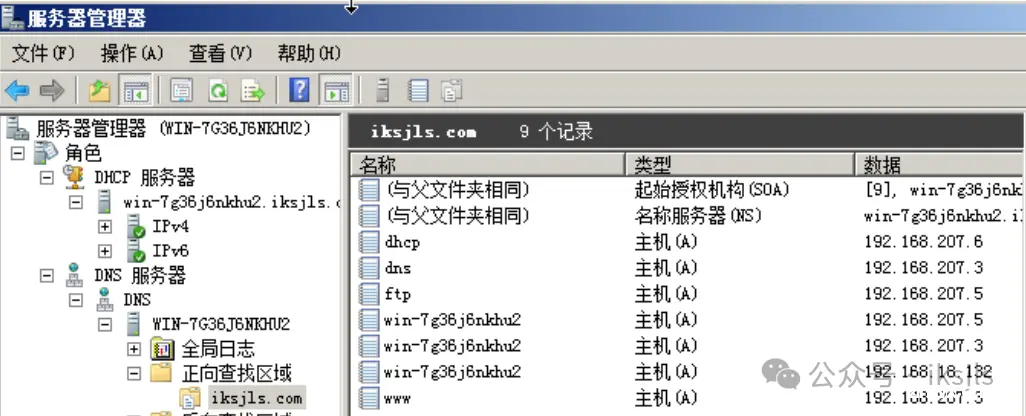
并同时在反向查找域建立“新建指针(PTR)”添加记录1“www.iksjls.com”、记录2“dhcp.iksjls.com”、记录3“ftp.iksjls.com”相对应正向查找域记录。
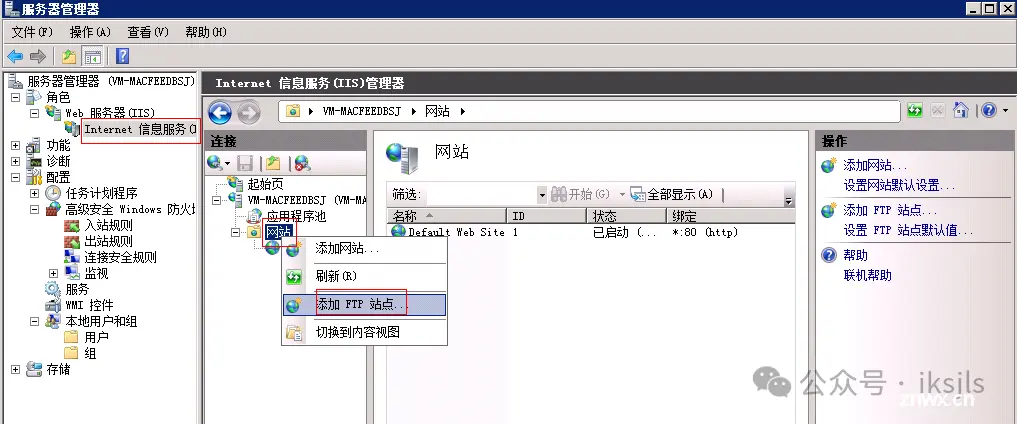
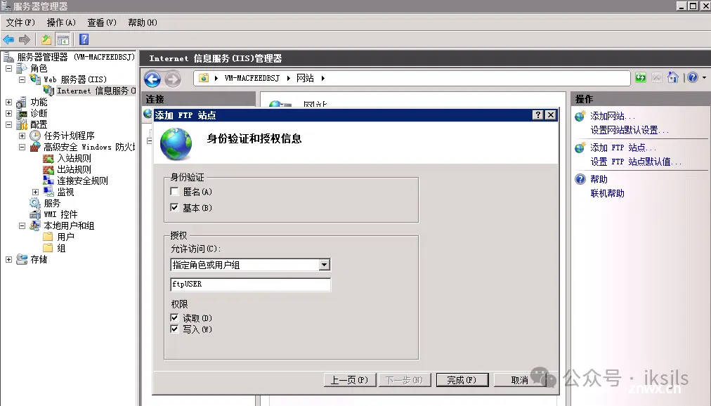
3.2.3 FTP
一、安装ftp服务
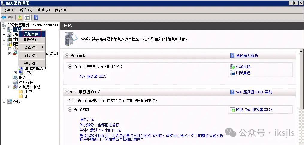
1、在服务管理器“角色”右键单击“添加角色”。
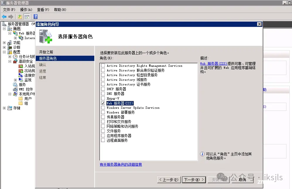
2、勾选“Web服务器(IIS)”,下一步
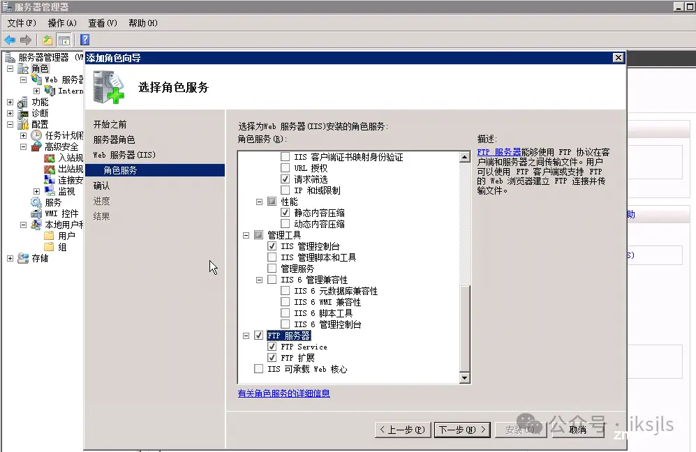
3、勾选“FTP服务器”,下一步。
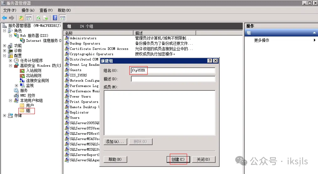
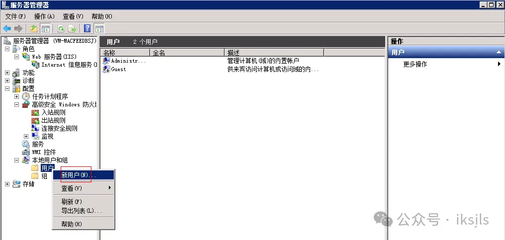
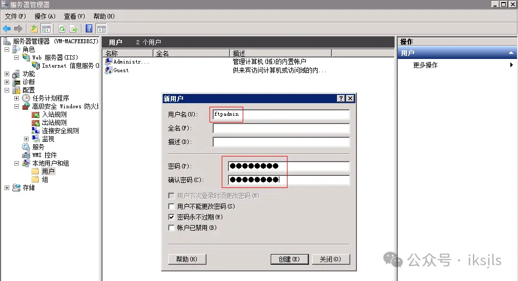
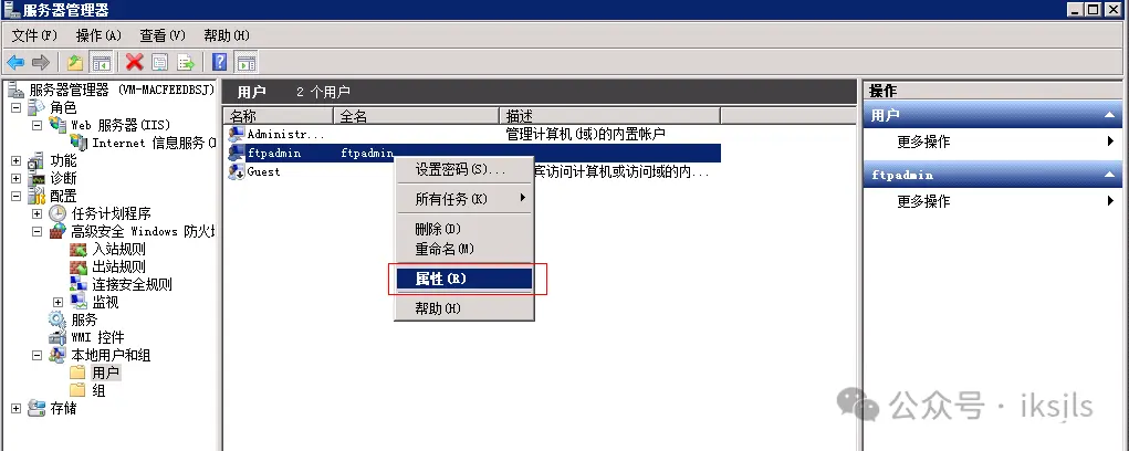
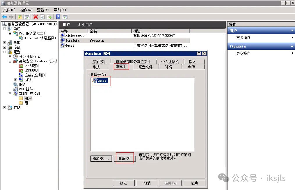
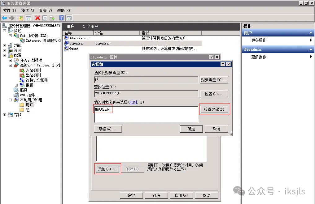
二、创建新组ftpUSER和新用户ftpadmin
1、右键单击“组”,新建一个组ftpUSER。
2、右键单击“用户”,创建一个用户ftpadmin。
3、更改ftpadmin用户的组为ftpUSER
三、添加FTP站点
3.2.4 DHCP
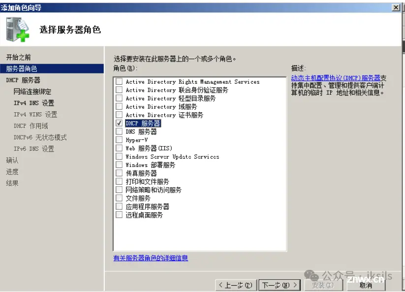
服务器角色选择DHCP服务器
根据需求新建作用域

添加地址排除范围

四、项目测试结果
4.1 服务器测试
4.1.1 DNS
4.1.2 DHCP
4.1.3 FTP
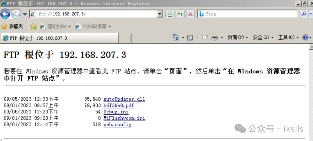
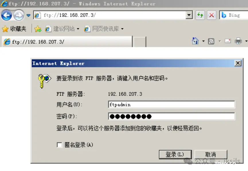

4.1.4 WEB

4.2 网络测试
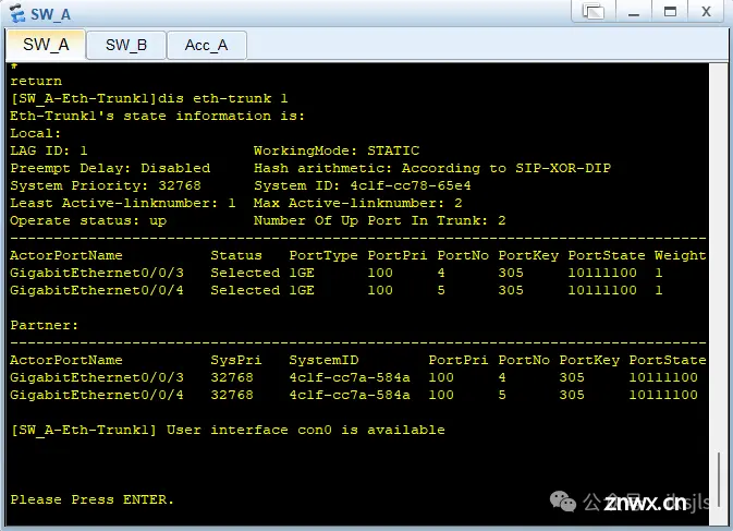
4.2.1 链路聚合
验证配置结果
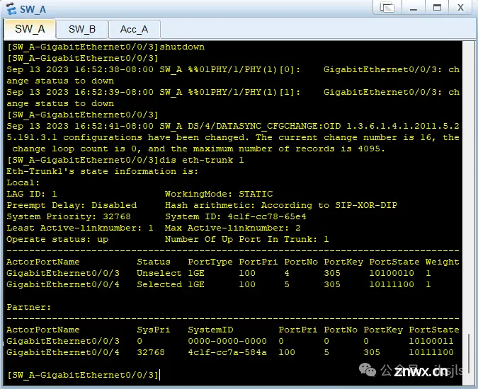
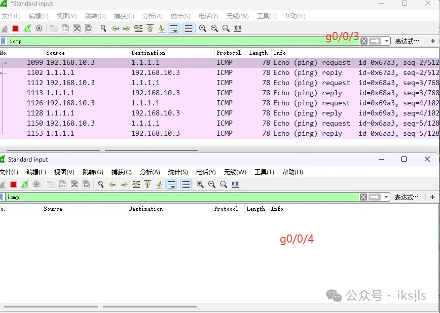
当SW_A的G0/0/3口断开时,链路状态
通过抓包可以发现

在阻塞g0/0/1的基础上,本来从PC1(192.168.10.3/24)到Internet1 的loopback 1(1.1.1.1/32)走的是g0/0/3端口
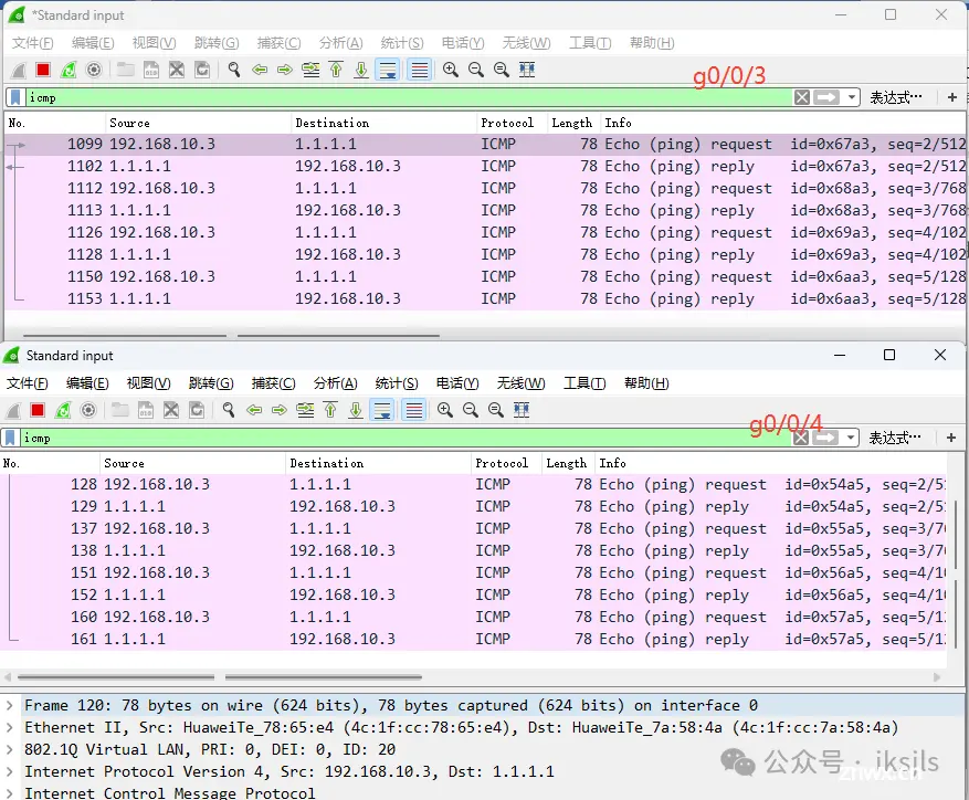
当我把SW_A的G0/0/3端口阻塞时,通过抓包可以发现自动切换到g0/0/4

两设备间的链路具有1条冗余备份链路,当活动链路出现故障时,备份链路 替代故障链路,保持数据传输的可靠性
4.2.2 主备备份
当SW_A和SW_B都正常运行且链路的状态都处于正常工作的情况下,通过抓包可以发现从PC1(192.168.10.3/24)到Internet1 的loopback 1(1.1.1.1/32)经过的是SW_A,而SW_B作为备份
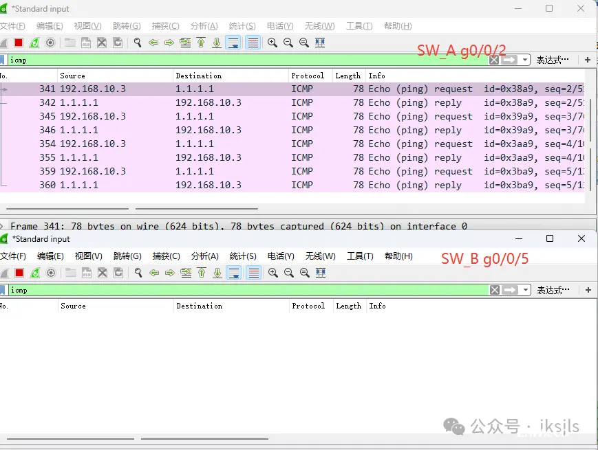
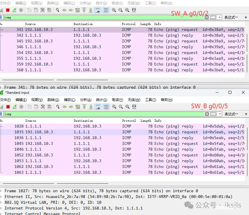
当SW_A发生故障时

作为备份的SW_B立即投入使用
4.2.3 远程登录
在SW_A配置telnet
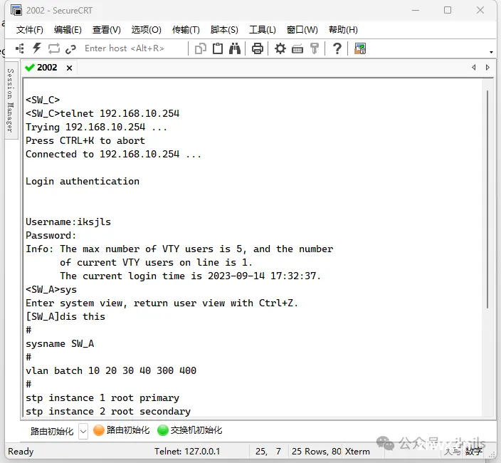
使用secure CRT在SW_C成功登录到SW_A
五、项目总结和体会
在此项目中,我为某企业设计并实现了双出口局域网,结合了多种网络技术,包括三层交换机、RIP、MSTP、VRRP、链路聚合以及VTP、VLAN等,旨在提供高效、稳定的网络环境。
首先,项目的最核心部分是建立双核心网络。我使用三层交换机来接入两个互联网链路——Internet1和Internet2,通过负载均衡技术确保网络的高可用性和稳定性。ospf协议的采用使得网络设备能够动态地发现和更新路由,保障了数据传输的顺畅。MSTP技术用于避免网络中的环路,提高网络的可靠性。VRRP是一种容错协议,用于在主备路由器之间无缝切换,保障网络的连续可用性。
其次,为了提高网络的安全性,我使用了访问控制列表ACL,限制了网络资源的访问,有效防止了非法访问和攻击。
在服务器区域规划方面,我为该企业部署了基于Windows server 2008操作系统的WEB、DNS,以及FTP和DHCP服务器。这些服务器可以提供各种网络服务,满足企业的各类需求。
最后,我对企业的四个主要部门——人力资源部(V10)、市场营销部(V20)、财务部(V30)、信息部(V40)进行了详细的网络规划和设计。通过VLAN技术,将各部门的数据流量隔离,避免部门之间的数据泄露和干扰。同时,通过telnet技术,我实现了对各部门网络拓扑的远程管理和维护。
这个项目让我深刻理解了网络设计的复杂性和必要性。在实际操作中,我遇到了一些挑战,比如负载均衡和容错协议的配置、网络安全措施的实施、服务器的部署和配置等。但通过的合作和专业知识的应用,我成功地克服了这些困难,使这个项目得以顺利完成。
声明
本文内容仅代表作者观点,或转载于其他网站,本站不以此文作为商业用途
如有涉及侵权,请联系本站进行删除
转载本站原创文章,请注明来源及作者。